

An electric motor turns because of magnetic force exerted between a stationary electromagnet called the stator and a rotating electromagnet called the rotor. Different types of electric motors are distinguished by how electric current is supplied to the moving rotor. In a DC motor and a slip-ring AC motor, current is provided to the rotor directly through sliding electrical contacts called commutators and slip rings. In an induction motor, by contrast, the current is induced in the rotor without contacts by the magnetic field of the stator, through electromagnetic induction. An induction motor is sometimes called a rotating transformer because the stator (stationary part) is essentially the primary side of the transformer and the rotor (rotating part) is the secondary side. Unlike the normal transformer which changes the current by using time varying flux, induction motors use rotating magnetic fields to transform the voltage. The current in the primary side creates an electromagnetic field which interacts with the electromagnetic field of the secondary side to produce a resultant torque, thereby transforming the electrical energy into mechanical energy. Induction motors are widely used, especially polyphase induction motors, which are frequently used in industrial drives.
Induction motors are now the preferred choice for industrial motors due to their rugged construction, absence of brushes (which are required in most DC motors) and—thanks to modern power electronics—the ability to control the speed of the motor.
History
The idea of the rotating magnetic field was developed by Francois Arago (1824) and implemented first by Walter Baily. The practical induction motors were independently realized by Galileo Ferraris, in Italy, and Nikola Tesla, in the United States. Tesla had conceived the rotating magnetic field principle in 1882 and used it to invent the first brushless AC motor or induction motor in 1883. Ferraris developed the idea in 1885. In 1888, Ferraris published his research in a paper to the Royal Academy of Sciences in Turin where he detailed the theoretical foundations for understanding the way the motor operates. Separately, in the same year, Tesla gained U.S. Patent 381,968. The induction motor with a cage was invented by Mikhail Dolivo-Dobrovolsky about a year later.
Principle of operation and comparison to synchronous motors
The basic difference between an induction motor and a synchronous AC motor with a permanent magnet rotor is that in the latter the rotating magnetic field of the stator will impose an electromagnetic torque on the magnetic field of the rotor causing it to move (about a shaft) and a steady rotation of the rotor is produced. It is called synchronous because at steady state the speed of the rotor is the same as the speed of the rotating magnetic field in the stator.
By way of contrast, the induction motor does not have any permanent magnets on the rotor; instead, a current is induced in the rotor. To achieve this, stator windings are arranged around the rotor so that when energised with a polyphase supply they create a rotating magnetic field pattern which sweeps past the rotor. This changing magnetic field pattern induces current in the rotor conductors. These currents interact with the rotating magnetic field created by the stator and in effect causes a rotational motion on the rotor.

However, for these currents to be induced, the speed of the physical rotor must be less than the speed of the rotating magnetic field in the stator (the synchronous frequency ns) or else the magnetic field will not be moving relative to the rotor conductors and no currents will be induced. If by some chance this happens, the rotor typically slows slightly until a current is re-induced and then the rotor continues as before. This difference between the speed of the rotor and speed of the rotating magnetic field in the stator is called slip. It is unitless and is the ratio between the relative speed of the magnetic field as seen by the rotor (the slip speed) to the speed of the rotating stator field. Due to this, an induction motor is sometimes referred to as an asynchronous machine.
Synchronous speed
Understanding the behaviour of induction motors, it's useful to understand the differerences from a synchronous motor. That type of motor always runs at a synchronous speed- a shaft rotation frequency that is an integer fraction of the supply frequency. The synchronous speed of an induction motor is the same fraction of the supply.
It can be shown that the synchronous speed of a motor is determined by the following formula:

- where ns is the (synchronous) speed of the rotor (in rpm), f is the frequency of the AC supply (in Hz) and p is the number of magnetic poles.
For example, a 6 pole motor operating on 60 Hz power would have a speed of:

Note on the use of p - some texts refer to number of pole pairs per phase instead of number of poles per phase. For example a 6 pole motor, operating on 60 Hz power, would have 3 pole pairs. The equation of synchronous speed then becomes:
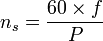
with P being the number of pole pairs.
Slip

The slip is a ratio relative to the synchronous speed and is calculated using:

Where
- s is the slip, usually between 0 and 1
- nr = rotor rotation speed (rpm)
- ns = synchronous rotation speed (rpm)
Construction
- The stator consists of wound 'poles' that carry the supply current to induce a magnetic field that penetrates the rotor. In a very simple motor, there would be a single projecting piece of the stator (a salient pole) for each pole, with windings around it; in fact, to optimize the distribution of the magnetic field, the windings are distributed in many slots located around the stator, but the magnetic field still has the same number of north-south alternations. The number of 'poles' can vary between motor types but the poles are always in pairs (i.e. 2, 4, 6, etc.).

There are three types of rotor:
* Squirrel-cage rotor
The most common rotor is a squirrel-cage rotor. It is made up of bars of either solid copper (most common) or aluminum that span the length of the rotor, and those solid copper or aluminium strips can be shorted or connected by a ring or some times not, i.e. the rotor can be closed or semiclosed type. The rotor bars in squirrel-cage induction motors are not straight, but have some skew to reduce noise and harmonics.
* Slip ring rotor
A slip ring rotor replaces the bars of the squirrel-cage rotor with windings that are connected to slip rings. When these slip rings are shorted, the rotor behaves similarly to a squirrel-cage rotor; they can also be connected to resistors to produce a high-resistance rotor circuit, which can be beneficial in starting
* Solid core rotor
A rotor can be made from a solid mild steel. The induced current causes the rotation.
Speed control

The synchronous rotational speed of the rotor (i.e. the theoretical unloaded speed with no slip) is controlled by the number of pole pairs (number of windings in the stator) and by the frequency of the supply voltage.
However, for a loaded rotor, for any given drive frequency and current and mechanical load, synchronous motors should be run in the 'operating zone' for that particular induction motor. This is the shaft rotation speed range above the peak torque. In this zone slightly increasing the slip speed increases the torque, and decreasing the slip decreases the torque. Hence in this zone the motor will tend to run at constant speed. Below the operating zone, the run speed tends to be unstable and may stall out or run at reduced shaft speed, depending on the nature of the mechanical load.
Before the development of economical semiconductor power electronics, it was difficult to vary the frequency to the motor and induction motors were mainly used in fixed speed applications. As an induction motor has no brushes and is easy to control, many older DC motors are now being replaced with THR induction motors and accompanying inverters in industrial applications.
Equivalent circuit
To understand the behavior of an induction motor when the rotational speed and supply frequency varies, it is helpful to look at the equivalent circuit. The equivalent circuit shows an electrically equivalent circuit to the motor's construction, where the two leftmost terminals would be connected to a power supply.

On the left side of the circuit, the equivalent resistance of the stator, which consists of the copper resistance and core resistance in series, is shown as Rs. During asynchronous operation, stator also induces some reactance, which is represented by the inductor Xs. The next inductor Xr represents the effect of the rotor (commonly a squirrel-cage) passing through the stator's magnetic field. The effective resistance of the rotor (again with rotating in a magnetic field), Rr, is composed of:
- the equivalent value of the machine's real power (which changes with the torque and the load on the machine)
- the ohmic resistance of the stator windings and the squirrel cage of shorted rotor windings.
At idle, the induction motor equivalent circuit is essentially just Rs and Xs, which is why this machine only takes up mostly reactive power. The idle current draw is often near the rated current, due to the copper and core losses which exist even at no load. In these conditions, this is usually more than half the power loss at rated load. If the torque against the motor spindle is increased, the active current increases by Rr, and thus in the rotor.
Due to the construction of the induction motor, the two resistances both induce a magnetic field, in contrast to the three-phase synchronous machine, where the magnetic flux is induced only by the reactive current in the stator windings.
The current produces a voltage drop in the cage portion of the Rr, but only a slightly higher voltage drop in the stator windings. Consequently, the losses increase with increasing load in the rotor faster than they do in the stator. The copper resistance Rs and the "copper" resistance from the cage portion of Rr both cause I2R losses, and therefore the efficiency of the machine improves with increasing load. The efficiency of the machine reduces with temperature.
In contrast with a smaller frequency of the reactance Xs also getting smaller. In compliance with the rated current must shrink by the drive voltage delivered. Thus, the ratio of the voltage divider Rs to Xs and Rs and this increases engine power losses. In continuous operation this can only be an approximation because a nominal torque is generated because the cooling of rotor and stator is not included in the calculation. At higher than the rated speed or rated frequency induction motor can, however - in the context of isolation - are working on higher voltages and is more effective.
Frequently today, Rs / Rr are measure automatically and are thus in a position for any motor connected to automatically configure itself and thus to be protected from overload. A holding torque or speed close to zero can be achieved with a vector control. Here, too though, there can be problems with cooling since the fan is usually mounted on the rotor.
Starting of induction motors
Single Phase
In a single phase induction motor, it is necessary to provide a starting circuit to start rotation of the rotor. If this is not done, rotation may be commenced by manually giving a slight turn to the rotor. The single phase induction motor may rotate in either direction and it is only the starting circuit which determines rotational direction.
For small motors of a few watts, the start rotation is done by means of one or two single turn(s) of heavy copper wire around one corner of the pole. The current induced in the single turn is out of phase with the supply current and so causes an out-of-phase component in the magnetic field, which imparts to the field sufficient rotational character to start the motor. Starting torque is very low and efficiency is also reduced. Such shaded-pole motors are typically used in low-power applications with low or zero starting torque requirements, such as desk fans and record players.
Larger motors are provided with a second stator winding which is fed with an out-of-phase current to create a rotating magnetic field. The out-of-phase current may be derived by feeding the winding through a capacitor or it may derive from the winding having different values of inductance and resistance from the main winding.
In some designs, the second winding is disconnected once the motor is up to speed, usually either by means of a switch operated by centrifugal force acting on weights on the motor shaft or by a positive temperature coefficient thermistor which, after a few seconds of operation, heats up and increases its resistance to a high value thereby reducing the current through the second winding to an insignificant level. Other designs keep the second winding continuously energised when running, which improves torque.
No comments:
Post a Comment